Suspension-Driven Antenna Deployment Mechanism
A linkage that deploys the rover's antenna using suspension travel instead of a dedicated motor.
01Problem
Poly1Rover needed a way to deploy its antenna reliably in the field. A dedicated deployment motor was the obvious default, but it would add mass, another point of failure, and another subsystem to power and control — resources the rover couldn't spare.
02Requirements / Constraints
- Deploy the antenna smoothly and under control, without a dedicated deployment motor.
- Integrate with the rover's existing suspension system and packaging.
- Be manufacturable with the team's available 3D printing and fabrication methods.
03Concept Development
The concept centers on borrowing motion the rover already has: suspension travel. A linkage translates that travel into the motion needed to drive a ratchet-and-pawl mechanism, which advances the antenna into its deployed position step by step as the suspension moves.
04Design
The design pairs a suspension-driven linkage with a ratchet-and-pawl deployment mechanism, so the antenna advances in controlled increments rather than deploying all at once. This removes the need for a dedicated motor and reduces overall system complexity.
05CAD / Analysis
The mechanism was modeled and iterated in SolidWorks, checking linkage geometry, clearances, and integration with the rover's suspension travel before committing to a prototype.
06Prototyping
Prototypes combined 3D-printed parts with hand-fabricated components, letting the linkage and ratchet mechanism be evaluated on the bench and on the rover.
07Testing
Prototype iterations were evaluated for fit, manufacturability, and integration with the rover, cycling the suspension through its travel to check that the ratchet-and-pawl mechanism advanced the antenna smoothly and repeatedly.
08Iteration
Each round of testing fed back into the linkage geometry and pawl engagement, improving fit and manufacturability across prototype revisions.
09Final Design / Outcome
The final mechanism deploys the antenna using rover suspension travel alone, eliminating the need for a dedicated deployment motor and reducing overall system complexity.
10Key Results
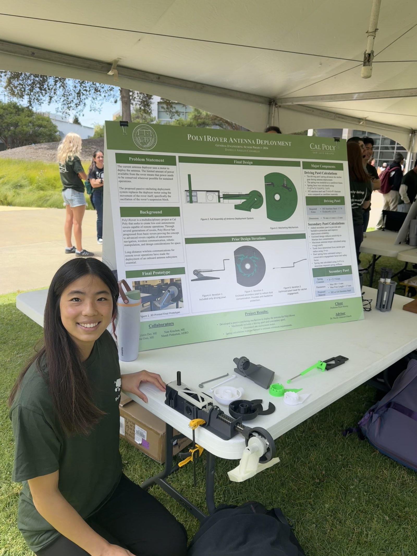
I was selected to represent the team at Cal Poly's Engineering Expo and present the design and technical work behind this mechanism.
11What I Learned
Add a short technical reflection here — what you'd carry forward from designing a mechanism that repurposes an existing subsystem's motion instead of adding a new actuator.